When it comes to choosing a battery-powered motor, various types of motors may be considered. Today, most battery-powered devices use three-phase brushless DC (BLDC) motors for their higher efficiency and smoother power delivery, making them ideal for high-power and industrial applications. In this blog, we discuss what you need to know when choosing motor control solutions for your battery-powered application.
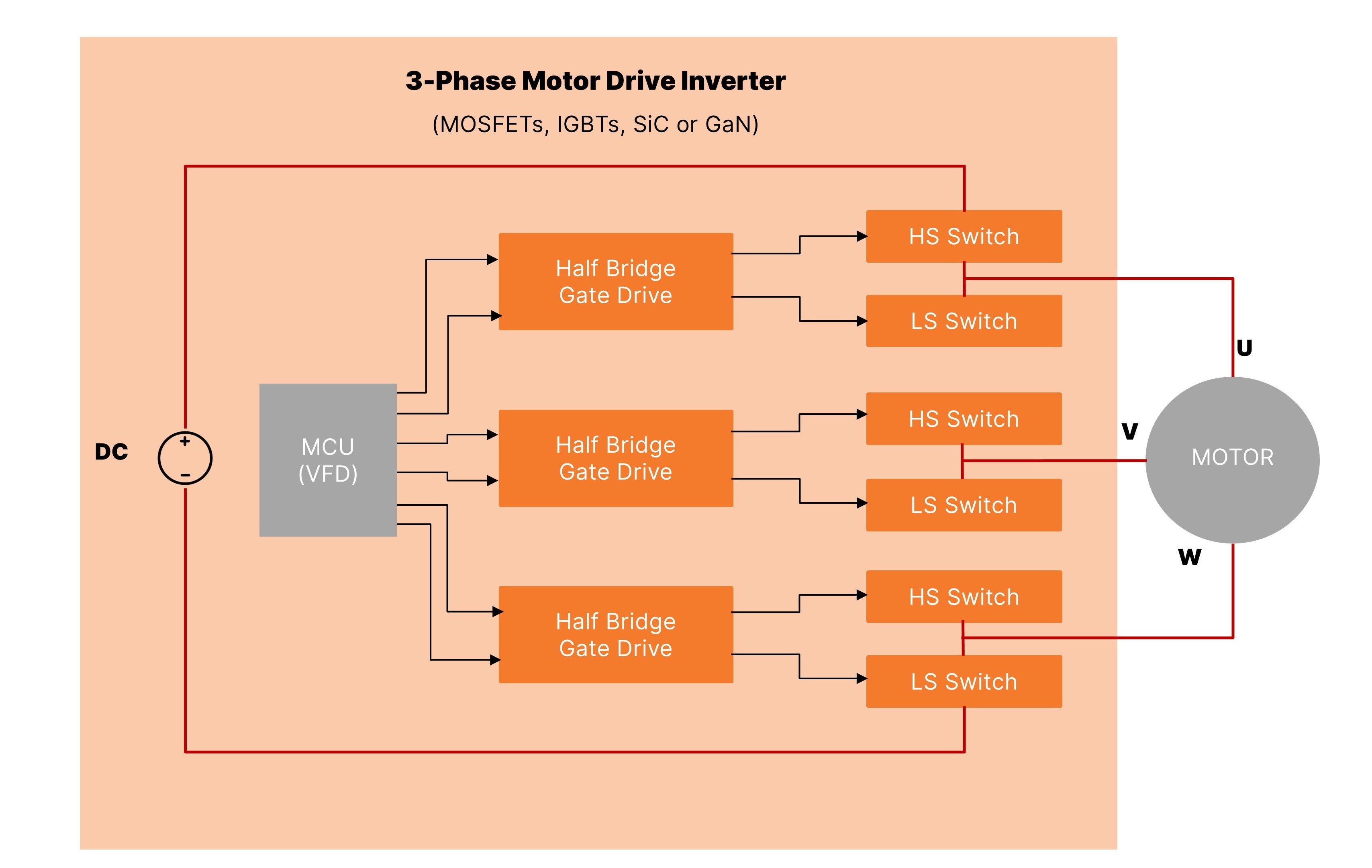
To get started on a new design, you should know that every motor needs a motor controller to precisely control the speed and torque. The motor control system is comprised of three major subsystems (see Figure 1 below). First is the controller (e.g., MCU). The output of which is a low voltage pulse-width modulated (PWM) signal used to establish the speed of the motor. Next is the gate driver, which takes the low voltage output from the controller and amplifies the voltage and current so it can drive a switch. Finally, the switches alternately supply voltage/current to the three windings in the motor that generates the torque.
Applications That Use Battery-powered Motors
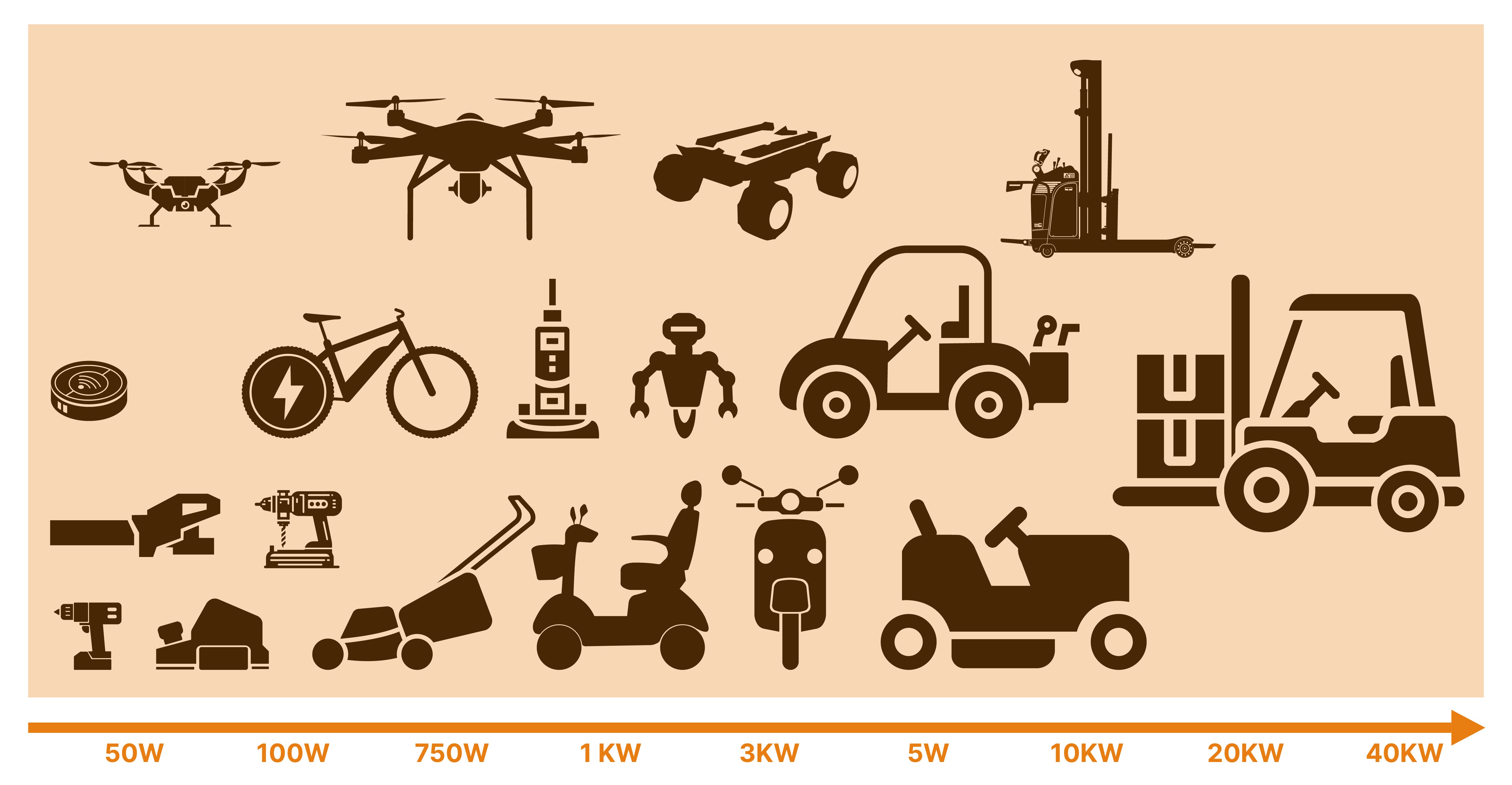
Battery-powered applications can be divided into two main categories: low voltage/low torque and high voltage/high torque. The reason we make this distinction is because these two require different products and solutions for motor control.
Low voltage applications (up to about 3 kW) include power tools (drills, sanders), garden tools (lawn mowers, leaf blowers) and drones on the low end. On the high end, this can include products like electric bikes, automation robots and mobility scooters.
High voltage applications (from 3 kW up to about 40 kW) range from electric scooters, automated guided vehicles (AGV) and golf carts on the low end, to autonomous mobile robots (AMR), electric tractors and electric/autonomous forklifts on the high end.
In motor control solutions, the choice of transistor type is crucial. For low voltage applications, transistors with lower breakdown voltage are preferred because of their smaller footprint and cost-effectiveness features. On the other hand, transistors with higher breakdown voltage are required to handle increased power demands and ensure reliable operation for higher voltage applications.
High-Level System Block Diagram
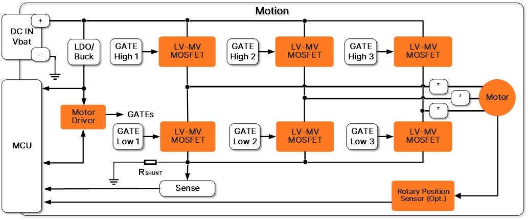
A typical system block diagram for a 3-phase BLDC motor is shown in Figure 3 below.
Operating a 3-phase BLDC motor requires a 3-phase inverter consisting of three half bridges for a total of six MOSFETs. The 3-phase full-bridge topology with proper control algorithms enable precise control over motor speed and direction, ensuring the efficient and reliable operation of battery-powered tools. The motor control function uses a PWM signal to determine the commutation between the ON and OFF states.
Gate drivers serve a critical role in controlling MOSFETs. They essentially translate low-power control signals from the motor controller or microcontroller into high-power signals capable of driving the MOSFETs effectively, ensuring the MOSFETs switch on/off rapidly and efficiently, enabling precise control over the motor's speed and direction. They also provide protection features such as overcurrent and overvoltage protection to safeguard the motor and the drive circuitry.
Position sensors measure the rotation of wheels or other moving parts to accurately track their position and orientation in their environment. They can be employed as part of the electronic commutation of the BLDC control. Inductive encoders offer many advantages over traditional optical or magnetic sensors. They are robust and lightweight - simplifying the overall design of circuits, and are not sensitive to vibration or contamination.
Critical Considerations
The industry continues to focus on improving motor controllers. There is a constant desire to make them smaller, more efficient, more reliable, and capable of driving more powerful motors. This requires enhancing the performance of the components and subsystems that make up the motor controller.
The starting point for any motor controller design has to be with the voltage rating of the switching transistor. The DC motor sets the required DC voltage, which determines the voltage rating of the switching transistors. These transistors need a safety margin above the required voltage. For field-effect transistors (FETs), the key rating is the maximum drain voltage (Vds). For example, a DC motor needing 100 VDC would use a FET with at least a 150 Vds rating to ensure a 50% safety margin, which is essential for high reliability.
The next consideration is efficiency (or power consumption). Power consumption in switching transistors comes from two sources: switching losses and conduction losses. Choosing the optimal combination of dv/dt and RDS(on) will generally result in the best power density for your motor controller. The effect is smaller size and extended battery life.
Only after you’ve settled on the appropriate transistor for your design can you move on to the gate driver. The required input voltage and current of the particular transistor will determine which driver to turn it on and off. Once the combination of transistor and driver is chosen, you can select additional components including the controller, LDOs, buck regulators, op amps and so on.
Products and Solutions for Optimal Performance
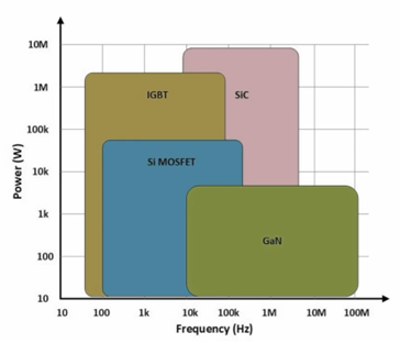
onsemi offers a variety of power semiconductor technologies for transistors with different power and speed as shown in Figure 4 below:
Silicon (Si) MOSFETs strike a balance between performance, cost, and thermal management, making them a practical choice for battery-powered applications. onsemi’s latest PowerTrench® technology, shield gate trench, offers ultra-low gate charge and RDS(on), which translates to lower switching and conduction losses. Consequently, the PowerTrench T10 family achieves both higher power density and reliability than previous technologies and is available in 40 V and 80 V solutions with multiple package options.
The choice of transistors will dictate the drivers to drive those transistors. You’ll want to consider whether you need an isolated gate driver—one that isolates the input and output of the driver. A general rule of thumb is if the motor power is less than 2.5 kW, then isolation is not needed. Otherwise, it’s best to choose an isolated driver as it avoids ground loops and protects users.
Other driver considerations include the amount of sink/source current required, operational supply voltage and whether you need an internal current sense amplifier.
Finally, there are two different design approaches when selecting a driver. There are single-phase drivers (called high/low drivers) which drive both transistors of one phase. For a three-phase motor you will need three of these. There are also three-phase drivers available which contain six drivers. These single products, like the FAN7888, drive the high/low side of all three phases of a motor.
When choosing transistors and drivers for a battery-powered application, there are many considerations. Having a partner, like onsemi, can help guide you through this process to ensure you make the most appropriate decisions.
To learn more about specific products and solutions, check out onsemi’s wide range of discrete LV-MV MOSFETs, gate drivers, motor drivers and rotary position sensors for motor control systems to power your next battery-powered application design.
Additional Resources:
PowerTrench T10 Family
Battery-Powered Tools System Solution Guide
Industrial Motor Drivers System Solution Guide
Smart and Mobile Robots System Solution Guide
